
Chevy Cobalt Boost Gauge Face Installation
Please Read First The following procedure is offered only as a general guide to the proper use and installation of replacement gauge faces and LED kit. The LED installation procedure in particular requires skills in soldering and particular car must be taken when handling the cluster to avoid damage. Even with the greatest care, damage may occur. Parts of this procedure depend on “feel” which can only be developed through experience and which cannot be described in these instructions. Read this entire instruction sheet and proceed only if you understand every step. The installer must accept all responsibility for any damage that may occur as a result of following this procedure, or any incidental damage that may result from installing the gauge face and led kit. No warranties, express or implied, are offered as to the suitability of following procedure as concerns any specific vehicle or any vehicle in general, nor to the suitability of the product purchased’ for any use. We strongly suggest you take your gauges or gauge cluster and your new custom gauge faces and led kit to a qualified speedometer service and electronics shop for installation. Black Cat Custom Automotive will not be responsible for damage caused by the installation of the new gauge faces or any direct or incidental damages caused by their use, including but not limited to, personal injury or damage to property. Check your local laws concerning the modification of the instruments in your car before proceeding, as well as your vehicle manufacturers’ warranty. As with any modification, only the owner can make the final determination whether their vehicle is safe to drive. A decision by the purchaser to keep and install the replacement gauge face and/or any other products will be deemed as acceptance of these conditions by the purchaser, installer and any users of this product, as well as acceptance of all responsibility for any consequences related to the use of any and all products purchased from Black Cat Custom.
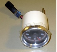
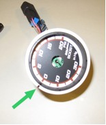
1. With the boost gauge out of the vehicle, start by applying the protective film to the front of the gauge and over the aluminum bezel ring. The film will protect the glass and the visible parts of the bezel.
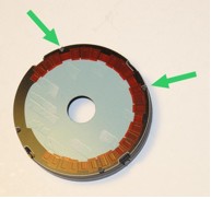 8. Mount the new gauge face to the trim ring by first noting the “zero” mark you made and lining up the zero on the new face with your mark. Slip two of the notches under the uncut tabs on the trim ring. If the new face does not sit snugly in place it may be necessary to use some glue to ensure it stays in place. Use a very small dab of glue, and apply it from the back side of the face so just a small amount gets in between the trim ring and the gauge face.
9. If you are not replacing the leds, skip to step 12.
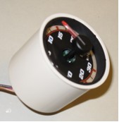
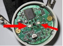
10. Replacing the leds requires a low wattage soldering iron. First, take note of the notch in the existing leds, as the new ones need to be put in the same way. To remove the leds, it’s best to use a desoldering tool or braid. If these are not available, remove the leds by first heating one side and lifting it just enough that the side is clear of the solder joint, then, while holding the led with tweezers, heat the other side and pull the led off when the solder melts. Repeat for the second led.
8. Mount the new gauge face to the trim ring by first noting the “zero” mark you made and lining up the zero on the new face with your mark. Slip two of the notches under the uncut tabs on the trim ring. If the new face does not sit snugly in place it may be necessary to use some glue to ensure it stays in place. Use a very small dab of glue, and apply it from the back side of the face so just a small amount gets in between the trim ring and the gauge face.
9. If you are not replacing the leds, skip to step 12.
10. Replacing the leds requires a low wattage soldering iron. First, take note of the notch in the existing leds, as the new ones need to be put in the same way. To remove the leds, it’s best to use a desoldering tool or braid. If these are not available, remove the leds by first heating one side and lifting it just enough that the side is clear of the solder joint, then, while holding the led with tweezers, heat the other side and pull the led off when the solder melts. Repeat for the second led.
 11. To install the new leds, hold the led in position – be sure that the notch is facing the right way – and solder one side. The first joint will hold the led in place so you can complete the second joint.
12. With the the new gauge face securely in place on the trim ring and the leds installed, replace the new face by pushing the circuit board back into the cluster to allow enough space for the face and trim ring.
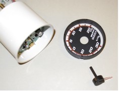
13. Line up the gauge face with your “zero” mark and slip it back into place.
14. Before replacing the needle, plug the gauge back in and turn the ignition on, but do not start the engine. Check that you new leds are lighting up, and with the power on, gently put the needle back on pointing at zero. Do not push it back into place yet, but instead turn the needle a bit in each direction and make sure it returns to zero with the power on.
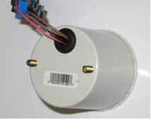
15. Disconnect the gauge and from the back, pull the mounting screws back until the works are back in place. Push the needle inward leaving a bit less than 1/8” clearance between the base of the needle and the gauge face. If the needle is to far up, it will stick on the glass cover. If it is too far in, it will stick on the gauge face, so you need to find just the right spot for it. You may need to put the front in place to check and adjust a few times.
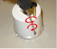
16. When the needle is properly replaced, put the cover and bezel back into place. Place the gauge front down on a firm surface. To re-seal the gauge, use a hard plastic, rounded tool….a screwdriver handle works well, and push the back edge of the bezel in toward the body of the gauge. Again, be sure to work from the back, to avoid leaving visible marks. Work your way around the gauge body until the bezel is firmly in place. Remove the protective film and replace the boost gauge assembly.
11. To install the new leds, hold the led in position – be sure that the notch is facing the right way – and solder one side. The first joint will hold the led in place so you can complete the second joint.
12. With the the new gauge face securely in place on the trim ring and the leds installed, replace the new face by pushing the circuit board back into the cluster to allow enough space for the face and trim ring.
13. Line up the gauge face with your “zero” mark and slip it back into place.
14. Before replacing the needle, plug the gauge back in and turn the ignition on, but do not start the engine. Check that you new leds are lighting up, and with the power on, gently put the needle back on pointing at zero. Do not push it back into place yet, but instead turn the needle a bit in each direction and make sure it returns to zero with the power on.
15. Disconnect the gauge and from the back, pull the mounting screws back until the works are back in place. Push the needle inward leaving a bit less than 1/8” clearance between the base of the needle and the gauge face. If the needle is to far up, it will stick on the glass cover. If it is too far in, it will stick on the gauge face, so you need to find just the right spot for it. You may need to put the front in place to check and adjust a few times.
16. When the needle is properly replaced, put the cover and bezel back into place. Place the gauge front down on a firm surface. To re-seal the gauge, use a hard plastic, rounded tool….a screwdriver handle works well, and push the back edge of the bezel in toward the body of the gauge. Again, be sure to work from the back, to avoid leaving visible marks. Work your way around the gauge body until the bezel is firmly in place. Remove the protective film and replace the boost gauge assembly.